My amps, a history?
Written on: 24jun'26 --- Updated on: n/a
A celebration of my amps :)
The first amp
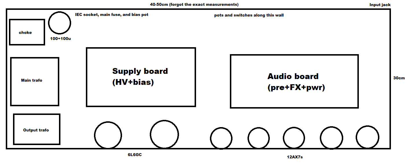
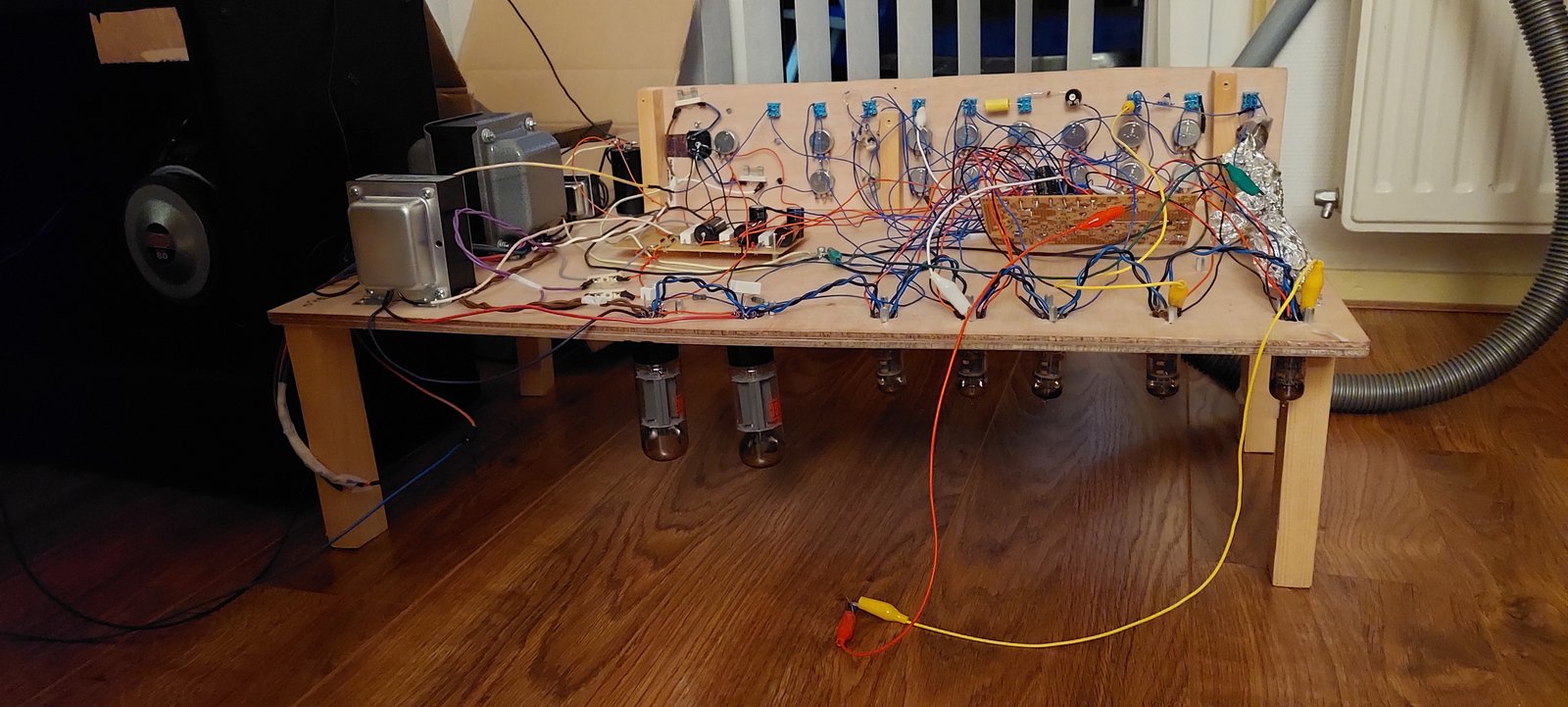
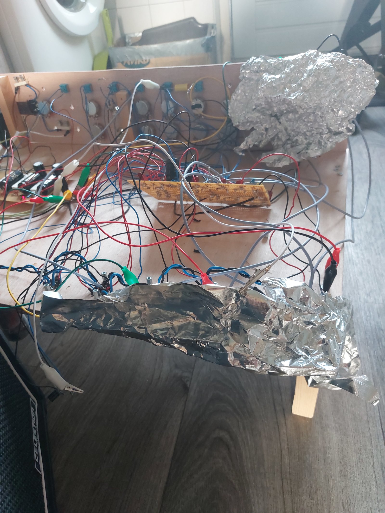
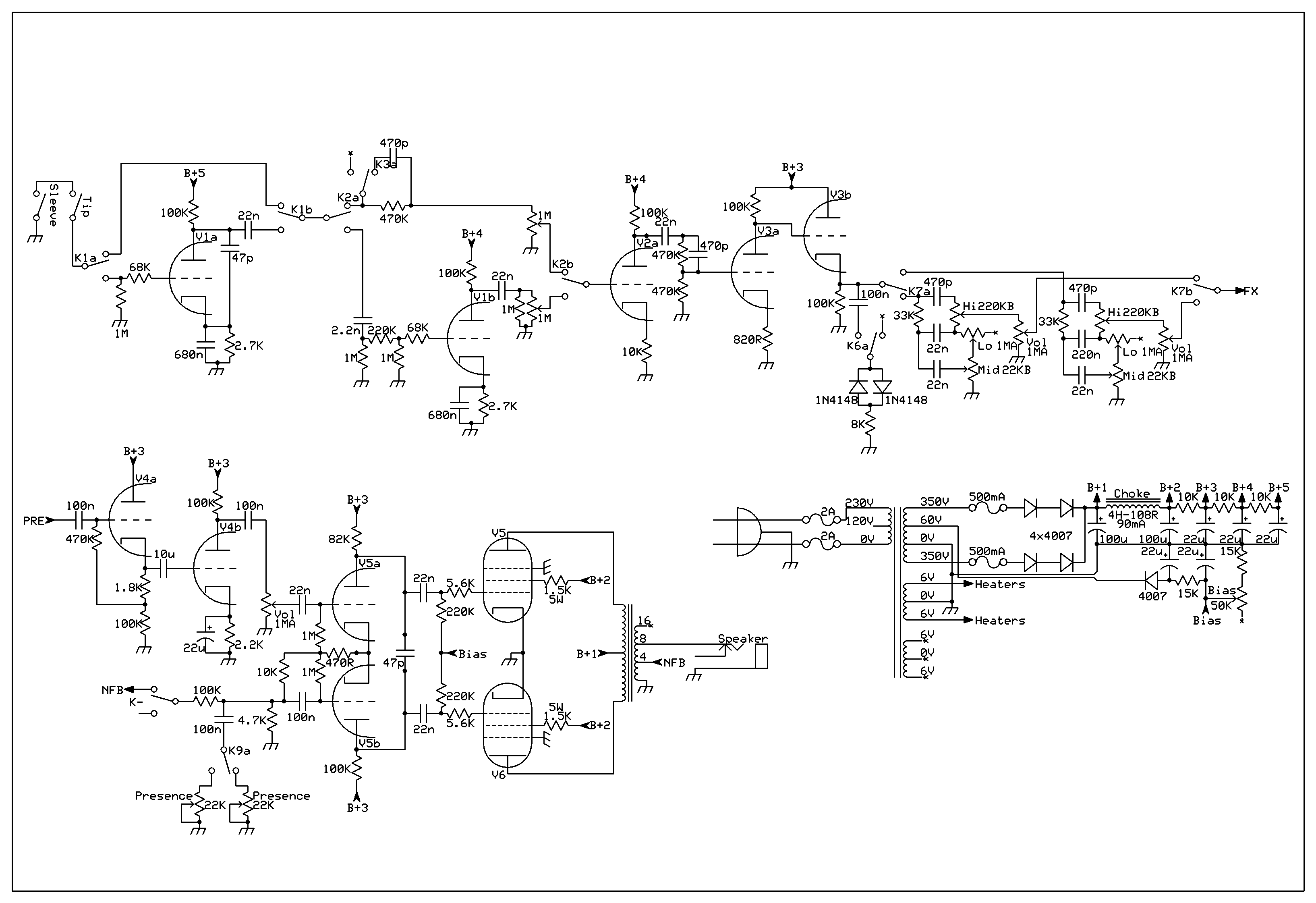
This one will be very short, I don't have much info about it actually. I built it... in 2021 I believe? It was a test bed of basically a 2203 horizontal input and Laney GH100L. It was made with a wooden table (because I was too lazy to use a metal anything), and it oscillated like crazy. Because of my inexperience, I also used 1N4148 diodes as a diode clipper, which I settled with 8k series resistance with. I'm not sure of the math, but methinks that gets it closer to the average 12V zeners.
If I ever find a schematic or pictures of it, I'll add them here, but it wasn't anything groundbreak; just imagine a GH100L with that boost stage switchable, the input stage switchable (like plugging into a low 2203), and NFB toggle+4n7||1Meg resonance. Oh, and the aforementioned 1N4148+8k diode clippers.
I just remembered another detail: a shitty FX loop that didn't work at all haha.
I FOUND THEM!!! [click on the images to view them better!]
->Here's the schematic of the first amp
The first REAL amp
And this is where we get into real business. I think this one was made a year later, I remember building it in the summer (like the previous amp) and sweating my balls off (also like the previous amp).
It was based on (err, cloned) an SLO-100 and RevE/F/G Rectifier, and thus named the RSLO! See this post for more info about the revisions. If you look at the schematic, you can once again see that it's a test bed for a lot of ideas, but they're not original ideas, just 'which part of the SLO do I like, and which part of the Rec do I like' kinda stuff. It sounded fine, but most switches (like the EQs set to modern, the NFB being off, or voltage always higher) I always set to certain positions.
So to give a rundown of the things I loved about it:
-It sounded big. Like every power chord and palm mute had heft to it. Having only owned a VC50 (first tube amp!) and VS100R (first amp!) at that point, it really felt special; the same tonal characteristics that made me fall in love with the Recto in the first place!
-The power amp direct out sounded very good. There was a time when I was using that as my main recorded sound (I can't remember if I used the 33n or 47n cap) with a 5 band PEQ after it into my mixer. Really worth trying!
-My first amp with PCBs as well, and thus far the only amp that hasn't been with PCBs was my first (which used perf board with copper pads drilled out for voltage isolation).
-A lot of the switches made big impact. You could add any of these switches to a Rec or SLO and you'd considerably change an amp, despite only changing one component (250k v. 500k gain pot) or changing entire functions (enable/disable NFB
-It gave me a lot of confidence, which you might not see anywhere, but after such a horrendous first built, building a high gain amp as a first/second amp and succeeding made me very happy. If it failed, I likely wouldn't have continued (and you wouldn't read about this!).
-it set me up to make, what I consider, my most original mod! (More about that later)
Now, I didn't like:
-My drilling sucked ass, I could only use a few of the planned screw holes for the PCBs.
-440V @ B+3 sounds nice, but as pointed out to me by a friend, tubes don't like that. Later on (in next amps) I'd stick to 400V for a healthier compromise.
-The power transformer I used didn't have a 12V tap, hence this build has been delegated to a test bed and will never be a proper amp.
-The layout is fiiiine, but it's not what I consider optimal. The Fender or 2203-era Marshall layouts are definitely worse, but with the tubes up front, you can't swap preamp tubes without taking the chassis out! Grr...
So here's the schematic, enjoy it, because this is what I would consider the last clone (for now?). [click on the images to view them better!]
->Here's the schematic of the second amp
The first REAL amp's future
So that amp you just read about, right? It has gotten rebuilt a year after it was built (again in the summer, funny) and named 'RECR3005'. I was chasing a problem at the time, which spoiler alert, turned out to be simply my room's resonance. Hence the rebuild was so... dissappointing. It removed the clean/crunch channel (which I am still very fond of), it removed the FX loop's jacks (god knows why), it removed the power amp direct out... You can really tell having a working amp rather than a perfect amp was more important at the time. It truly is a product of its time!
So what were the good changes? Thank you for asking that, let me introduce you:
-The bright/norm/dark switch is easily my most original mod. The norm or dark positions are very standard and boring, but take a look at the bright position; I still have no idea why that works, but it does. I originally found it by playing around with simulations, and all it really does is move the low pass cutoff lower and add volume to the typical bright cap peak. You can easily compensate for the cutoff change by halving the 470k gridstopper.
-The high/med/low switch is nothing that special in the grandscheme, and it's not even that good as described in the schematic. The 100p to ground sucks ass, 330k is too much cut, and 15k is boosted to much. I really do like it though, it adds a lot of flexibility to the overall circuit.
-The tonestack was changed from a very normal standard Recto Red Modern (100k presence, 680p treble cap) to being a hybrid between a Org and Red Modern (100k presence from Red, 470p treble cap from Org). For me this sets the mids in a better sweetspot, but ymmv.
-For the tonestack, I also added a 30p capacitor across the 470k between the treble wiper and tonestack volume. That added a lot of sizzle I was missing. Before it was a little 'damp' sounding, and after adding, it had the aggression I was missing.
-It featured my improved FX loop design, using a gigantic 4u7 630V capacitor for the coupling capacitor, significantly reducing any high pass effect. The loop will remain unchanged barring additional features.
-Later on, I did a mod: 100p across the V2b 470k resistor. This really livened up the amp in a very pleasant way. It still is very dark sounding, but it isn't shrill. That is, until you go to the high mode, that's when ideally that capacitor is across the 1Meg resistor just below it. It solves the overtone problem of the higher gain mode too!
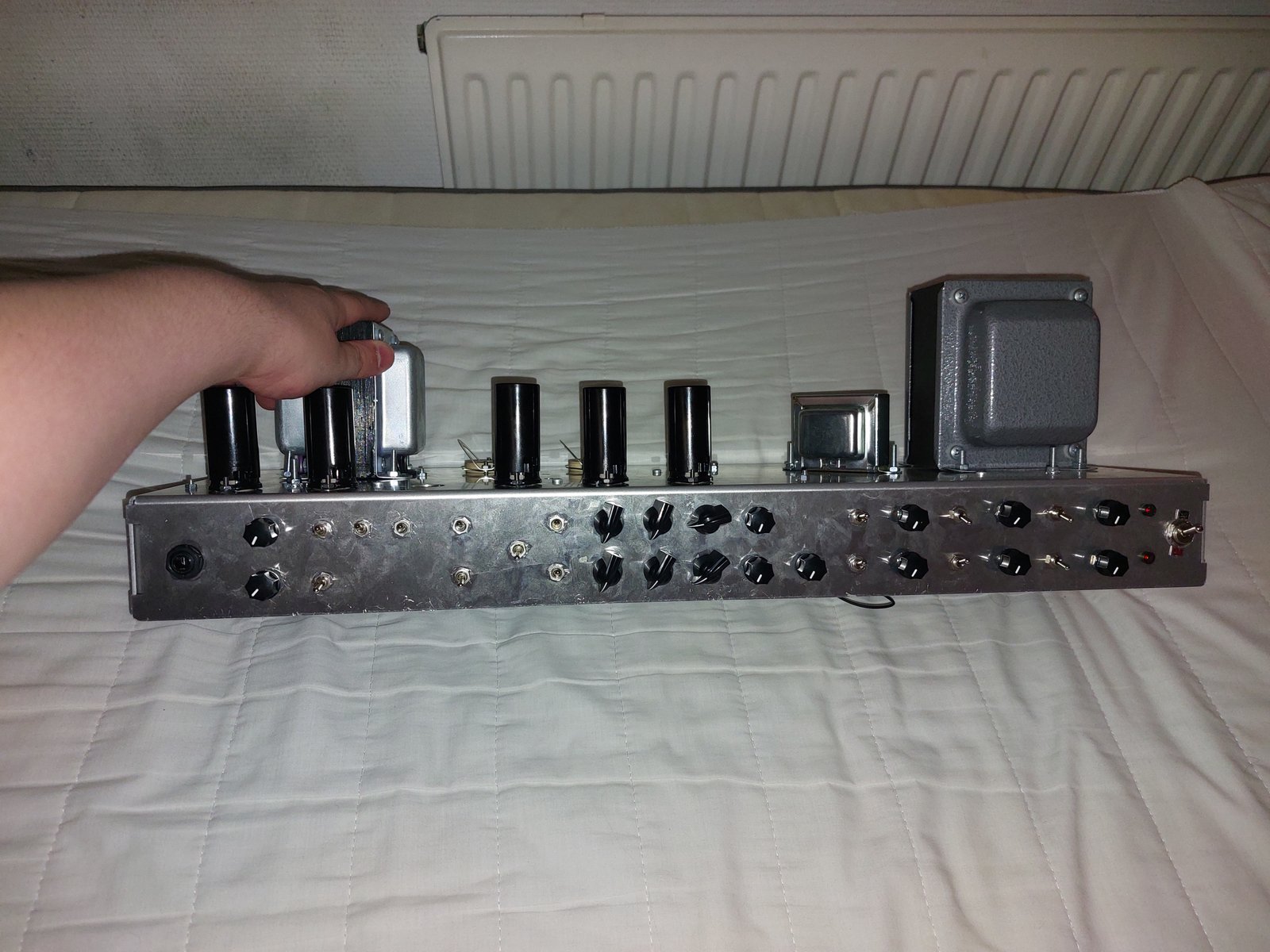
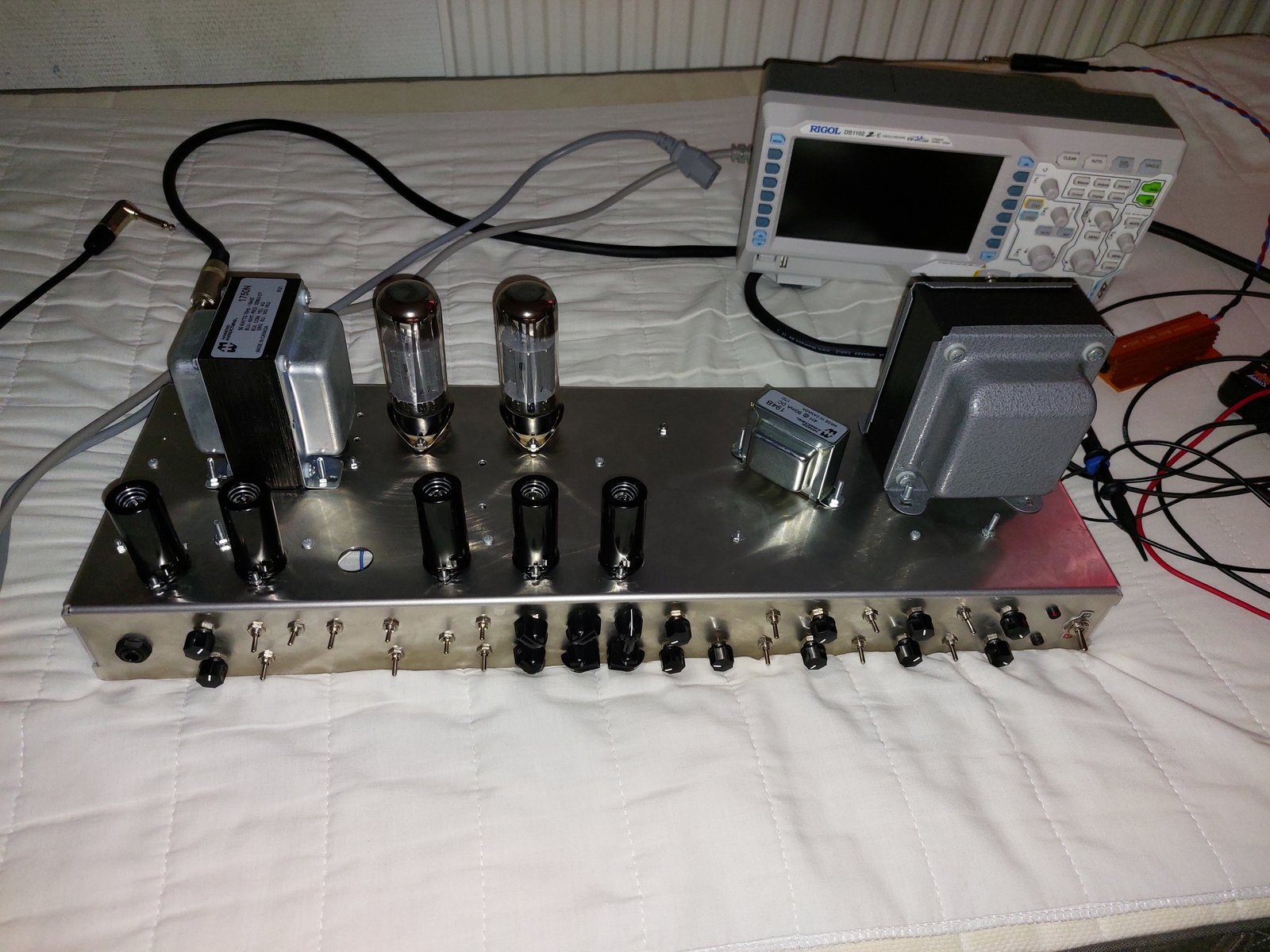
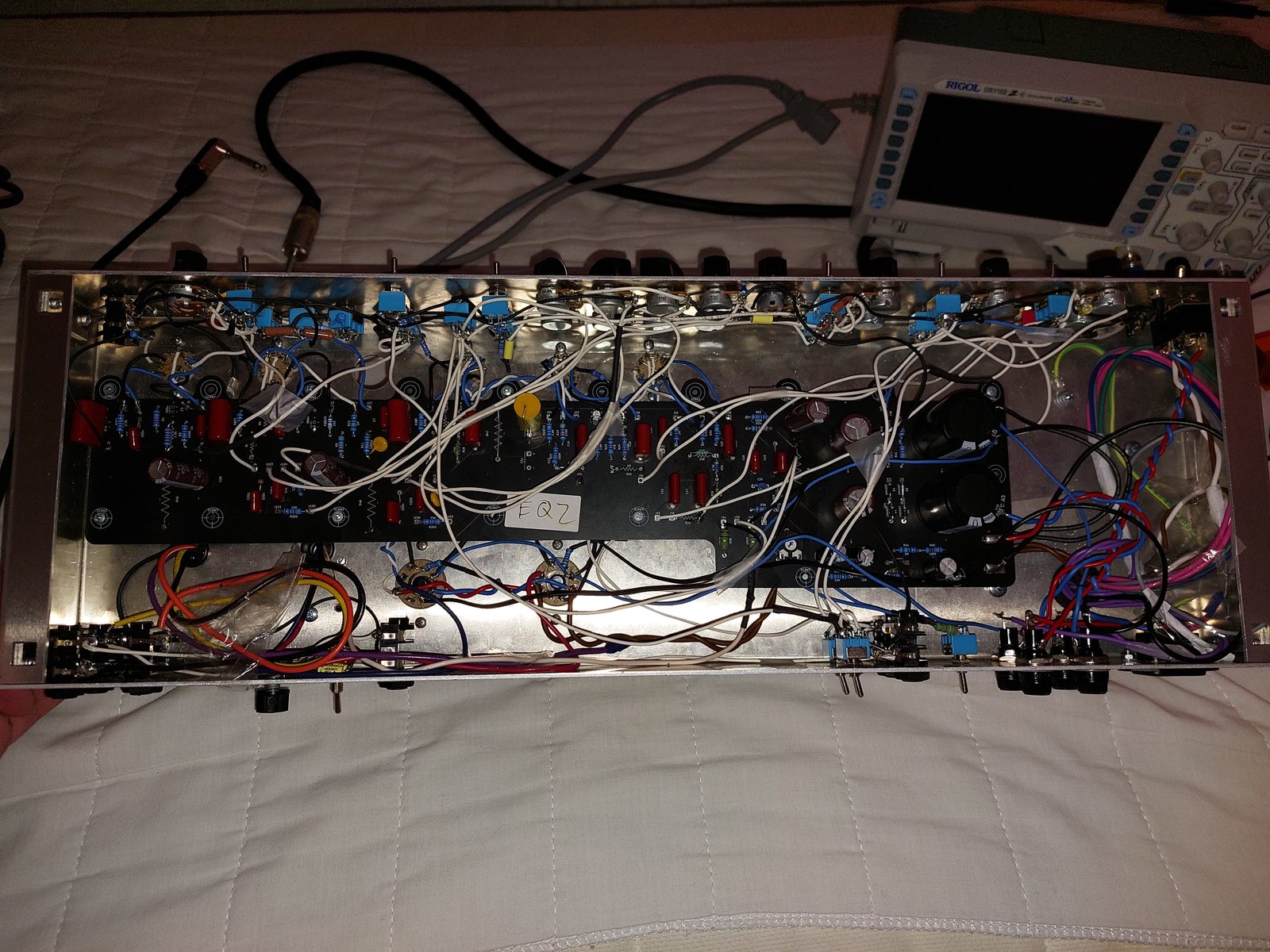
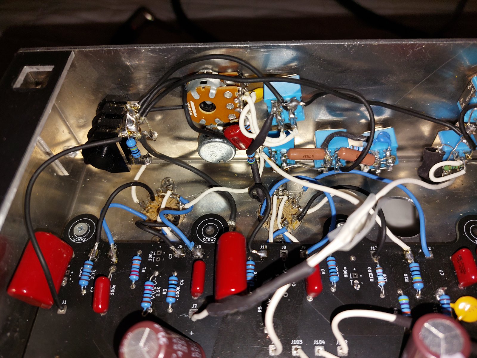
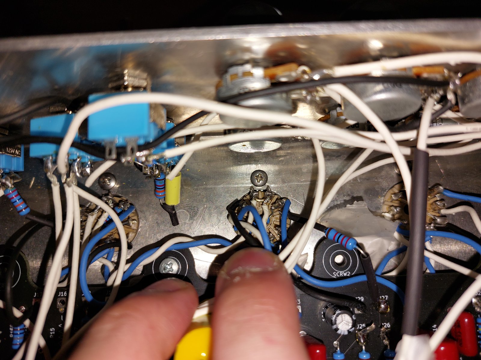
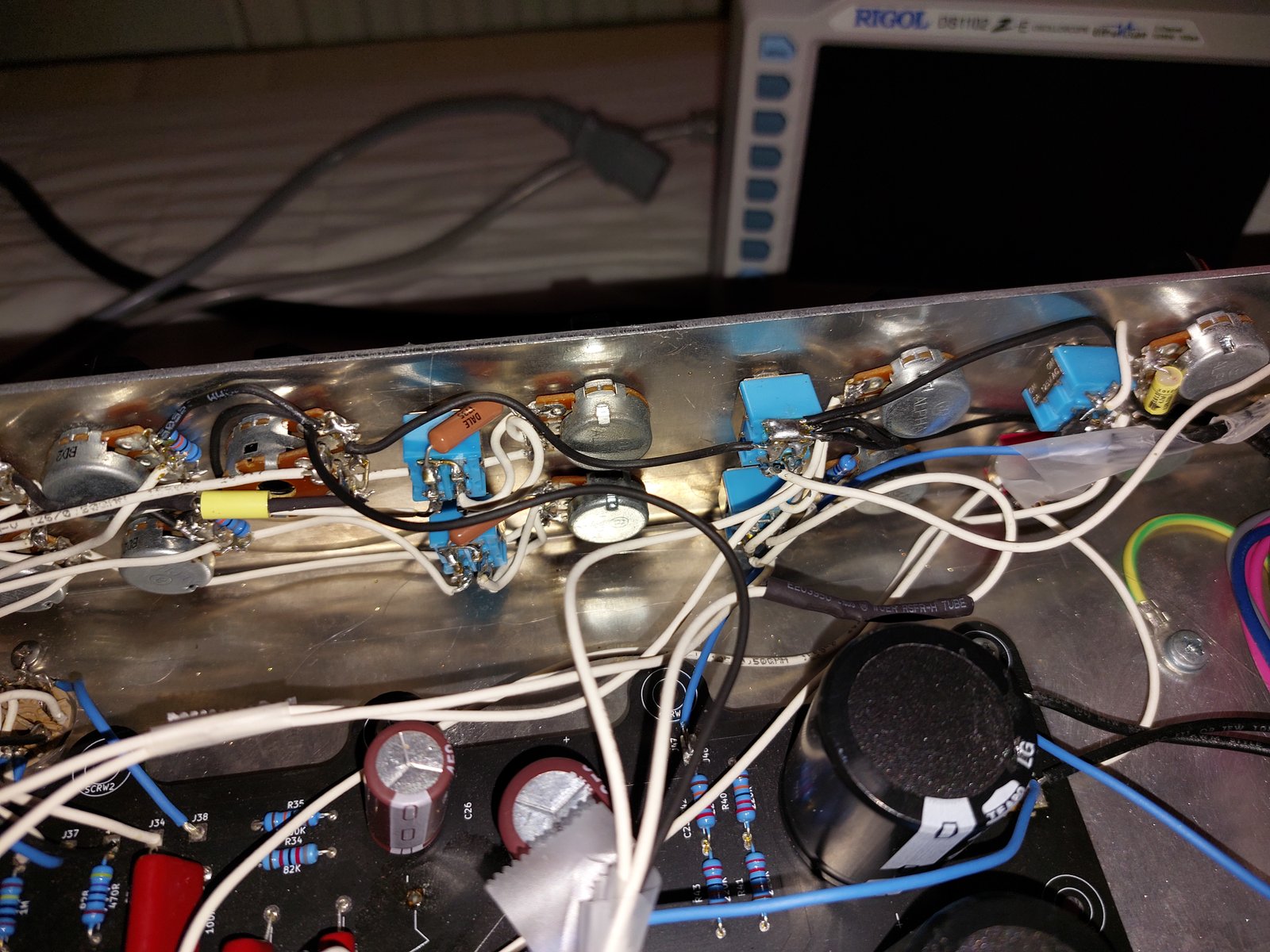
Because I still have this amp, here are some pictures, and here's the schematic too! [click on the images to view them better!]
->Here's the schematic of the second revised amp
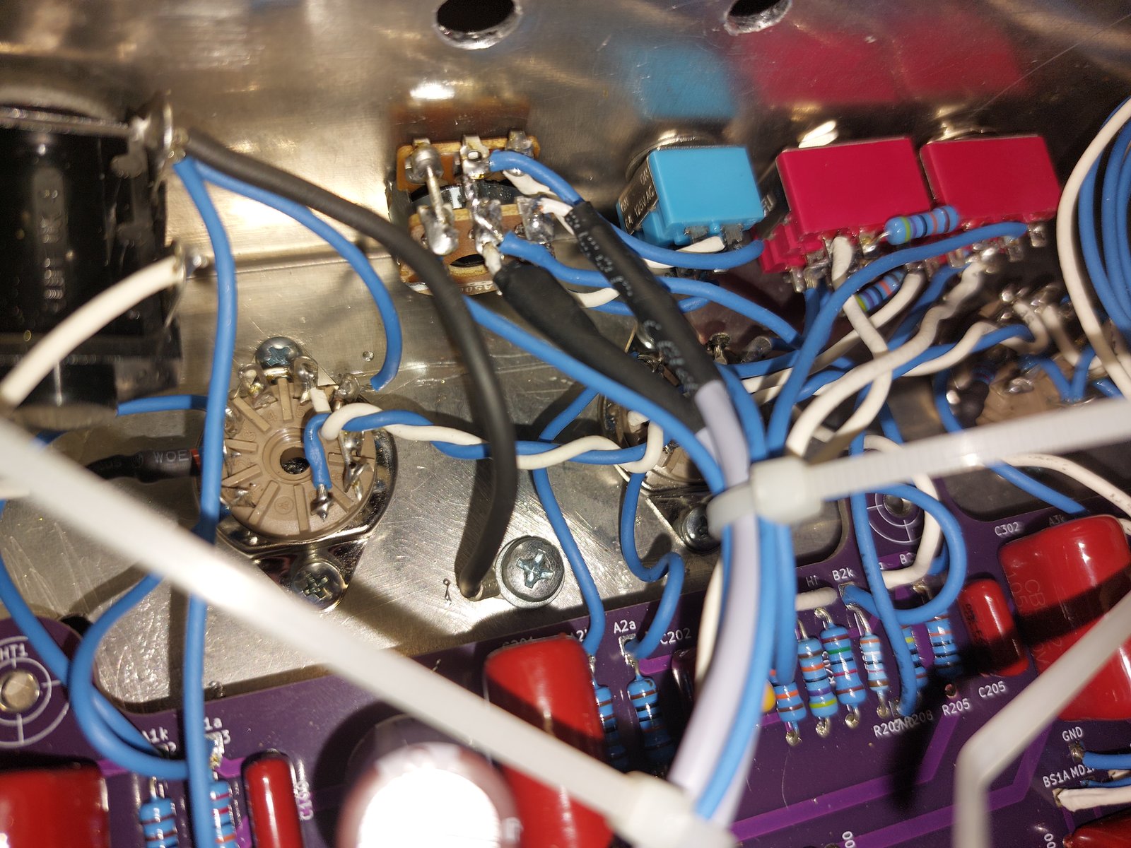
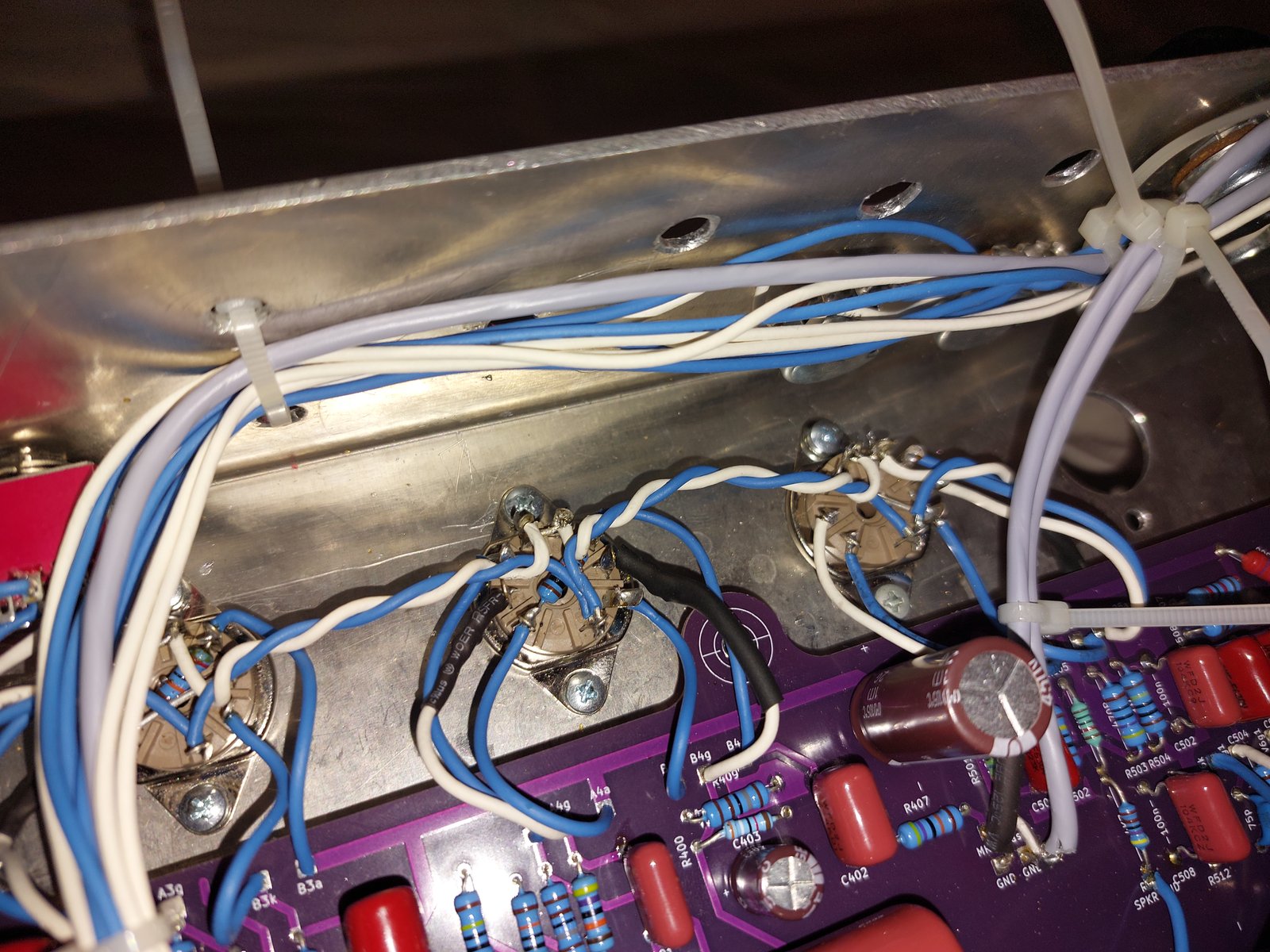
The spaghetti
This amp officially is named as the "MULTI3010" in my files, the name comes from many design iterations with overarcing series such as: VERY NEW AMPS 2000, VERY NEW AMPS 2008, VERY NEW AMPS 3000, and the VERY NEW AMPS 3010. I left some out. Anyway, why I call this one The Spaghetti is because I evidently just threw everything and saw what stuck. To satiate some curiosity: half the amp got cut :)
So what was the design philosophy around The Spaghetti? As the 'MULTI' part of the name suggests, it does more than one thing. That being... why did I add a Marshall/Laney and SLO/Rec to the same amp?! It's a very ambitious thing, and my god, it worked. Through the help of an Arduino Nano Every and 8x MCP23017s I had it switch between everything. Then you, the reader, would ask the question: which half got cut? And thank you my dear reader for reading this, but it's the Marshall/Laney ('british') side. I could never make it sound right, all it did was add many relays and a whole 'nother tube. The distortion texture was fuzzy (no matter of voltages or cathode resistances), the NFB just didn't sound right to me (it never did on the RSLO either), and neither did the matching tonestack. All in all, that part is a complete failure.
Speaking of failures, another failure was that the I2C data signals would leak into the audio path, creating whining. I changed all the I2C data and clock wires to shielded, but the bus capacitance makes the computer funky at power ons.
That just leaves us with the good part, the SLO/Rec! This is further built on the RECR and incorporates many of the shortcomings:
-The Clean/Crunch was readded! It also took a lot of inspiration from the Decatone as well, with its post-gainstage mid cut and the bypass cathode. The mid cut I am still not happy with (a bit too much), but the bypassed cathode would end up being used on the US Crunch+ mode.
-The high/med/low has been further refined. The 100p was implemented as the last point of the RECR's list, 330k was upped to 470k, and 15k was upped to 39k. These values sound boring (and it's because they are), but they sound the best, and I kinda hate that.
-The tonestack was refined even further. Now there's a resistor across one part of the treble wiper to brighten it up, and the 100k presence was made 50k.
-The FX loop got muting JFETs added (in the schematic it only shows before the buffer, but there's also one on the tiny daughterboard that's at the FX return's stage grid), and the FX trim and dual masters were added. The FX trim basically lets you boost +-1V. Going from (by memory) 0.4V to 2.4V with the master at noon.
-The voltages remain unchanged, still sitting at 400V and 375V at the nodes.
Other than that, it remains largely unchanged and is fairly close to the RECR.
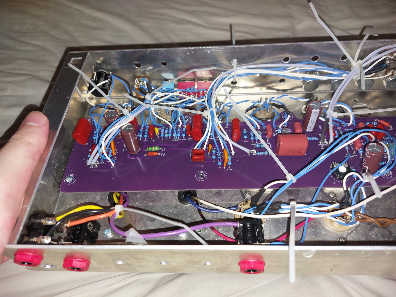
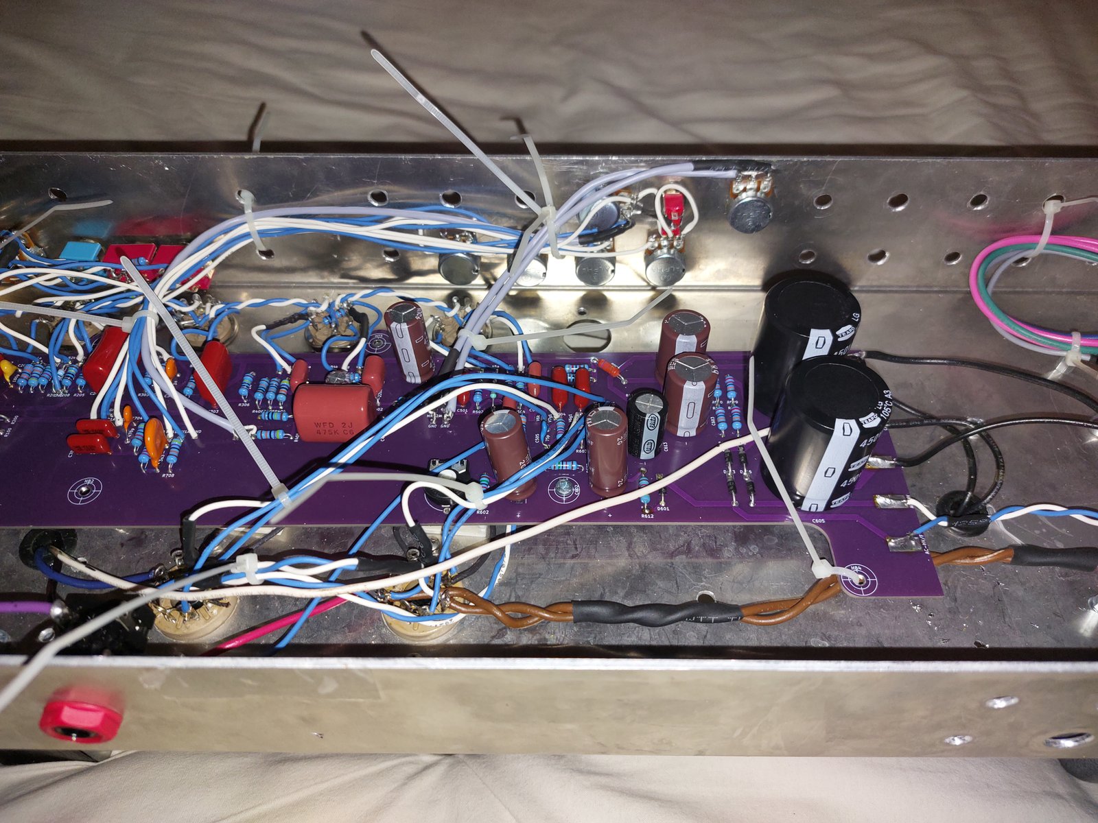
Here are some pictures of the amp, and schematics:
-This schematic has all the modes in simple stuff drawings, a lot of these would end up being changed.
-This schematic has all the PCBs
The noodles that stuck
The MULTI3010 might be the final amp in this lineage. I'm not saying that because I'm super confident I won't change my tastes, but I feel that any changes are simply value changes, not topology changes.
So what is the name of this amp? I don't know. Officially it's a revision of the MULTI3010, but spiritually it's a whole 'nother thang. The legal name would be BERY NEW AMPS 6010\RECR-5.75.3.3 3.95CH-15+2.1 KiCad8.0v2\RevX\REALLY SUPER FINAL REVISION\Prod revision (revC1 improved), which just sounds stupid. Mind you, the MULTI3010 is also in the "BERY NEW AMPS 6010" folder, yey for consistency.
Either way, what are the changes now?
-The UK High Gain gain stage got repurposed for a lead boost. The second UK gain stage got cut, so did the components around the cathode follower, and so did the NFB and UK tonestack.
-What was first two parallel gain stages (US clean/crunch, US high gain 2nd stage) has become the same gain stage, with a bunch of relays switching in different values for a fully 'amorphous gain stage'. This is my way of easily describing a gain stage that doesn't have an inherent function, and gets told what it is by setting a combination of relays. Nowadays you begin to see amorphous signal paths increase a lot, the latest Mesas like the Mk7 and Badlander are on the edge between conventional and amorphous too.
-The 'alt' switch still exists, but has been renamed to 'lead'. It used to switch between US/UK but now, as the name implies, does norm/lead. For each mode it adds a gain stage and cuts some amount of treble after the gain stages, with the High Gain Lead getting special treatment of adding a pad post-boost stage and and cutting a lot of treble in different places -- perfect for creamy solos!
-A switch, named Power Amp Mute has been added. If you couldn't tell, it mutes the power amp, but not in a conventional way. Conventional ways would be like cutting power to the anodes or muting the phase inverter or removing grounds from the cathodes... I however decided to do things differently and cut the power to the heaters. This is the same as pulling tube, which have a nasty consequence of increasing the anode voltage. I use a reed relay to pad the voltage down to +- the same.
The rest really hasn't changed much, the logic has gotten simpler, still the same FX and power amps (as implemented in the MULTI3010 build)... It's only the preamp, PCBs, and chassis that has gotten a (well-needed) overhaul.
The lost amps
It's funny that I've been doing things for so long, and I never deleted anything, yet still I managed to lose things.
-I have basically no information about my first amp, besides what is already mentioned.
-Another amp I have near-to-zero info on is what was supposed to be my third amp; audio-wise it's basically the RECR with an SLO clean/crunch, and circuit-wise it had an Arduino Micro for MIDI conversion but 555 timers, D-flip flops, and set/reset relays for channel switching. I actually have both PCBs and chassis made but the logic circuit failed to my standards, hence the whole build got shitcanned. I was going to redesign it and then I kept on adding things and redesigning until it morphed into the MULTI3010.